Executive Summary & Direct Decision Guidance:
A cabinet fire protection device serves as an internal, localized safety barrier designed to detect and suppress electrical fires directly at the point of origin before heat escapes into the wider facility. To ensure reliable performance, panel builders must evaluate eight core criteria: (1) verified protected volume against actual net cabinet geometry and internal leakage, (2) thermal activation sensitivity versus peak internal operating temperatures, (3) mechanical form factor and DIN-rail compatibility, (4) discharge dynamics and extinguishing kinetics, (5) environmental tolerance (temperature, relative humidity, vibration), (6) independent third-party fire test validation, (7) non-conductive residue and dielectric compatibility, and (8) total lifecycle cost. Conventional circuit breakers protect against electrical overcurrents, but fire suppression devices mitigate high-resistance thermal failures that do not trigger electrical trips.
Why Do Panel Builders Need a Cabinet Fire Protection Device?
Electrical control panels, low-voltage switchboards, and motor control centers (MCCs) house concentrated electrical connections, switching devices, power electronics, and busbars. In industrial and commercial facilities, an uncontained panel fire leads to severe financial consequences: extensive downtime, equipment destruction, production halts, and potential life-safety threats.
What Are the Main Fire Risks Inside Electrical Cabinets?
Electrical fires inside enclosed cabinets typically originate from thermal escalation scenarios rather than instantaneous dead shorts. The predominant root causes include:
- Loose Electrical Terminations and Localized Overheating: Cyclic thermal loading, mechanical vibration, and improper screw torque cause screw terminals and lug connections to loosen over time. This creates localized high resistance, causing junctions to exceed temperatures of 200°C to 500°C while carrying normal operating currents.
- Insulation Breakdown and Tracking Arcs: Prolonged exposure to operating heat, dust ingress, and atmospheric moisture degrades wire and busbar insulation, resulting in micro-arcing and surface carbonization tracking paths.
- Overloaded Circuits and Component Failures: Degrading relays, contactor coils, switching power supplies, and printed circuit board (PCB) components can experience internal thermal runaway.
- Thermal Dissipation of Power Electronics: Modern industrial panels frequently incorporate Variable Frequency Drives (VFDs), Soft Starters, and Solar Inverters. Restricted panel airflow or cooling fan failure allows ambient cabinet temperatures to rise rapidly, drying out plastic housings and accelerating component flammability.
Can Circuit Breakers Prevent Every Electrical Cabinet Fire?
A common misconception in panel design is assuming that Molded Case Circuit Breakers (MCCBs) or Miniature Circuit Breakers (MCBs) eliminate the need for internal fire suppression. Circuit breakers operate strictly on electrical parameters—specifically current magnitude over time (thermal-magnetic or electronic overcurrent and short-circuit trip curves).
When a loose wire termination exhibits high contact resistance, Joule heating ($P = I^2 \times R$) generates intense localized heat without drawing excess current. The continuous operating current remains well within the circuit breaker’s rated nominal capacity ($I_n$). As a result, the breaker will never trip, allowing surrounding wire jackets, plastic terminal blocks, and cable ducts to ignite. A cabinet fire protection device operates on thermal or chemical fire signatures, providing an autonomous layer of physical fire extinguishment that complements upstream electrical protection.
Which Electrical Enclosures Need Additional Fire Protection?
- Low-Voltage Main Distribution Boards (MDBs) & Sub-Distribution Boards: High current densities and complex cabling configurations make them vulnerable to continuous heating risks.
- Industrial Automation & PLC Control Panels: Housing critical process controls where single-point fires result in catastrophic plant downtime.
- Motor Control Centers (MCCs): High switching frequencies, magnetic contactor arcing, and heavy starting currents generate sustained thermal stress.
- Solar PV Combiner Boxes & Inverter Auxiliary Enclosures: DC electrical arcs are inherently difficult to self-extinguish and present heightened thermal hazards.
- Battery Energy Storage System (BESS) Auxiliary Cabinets: Supporting power electronics and control racks require localized suppression to prevent thermal propagation into adjacent battery modules.
What Should Panel Builders Check Before Selecting a Cabinet Fire Protection Device?
Selecting an effective electrical enclosure fire safety device requires moving beyond generic product claims. Panel builders, system integrators, and OEM buyers must rigorously verify the following eight technical parameters:
1. What Protected Volume Does the Device Support?
Every automatic fire suppression device is rated to protect a maximum geometric volume. Panel builders must first compute the internal volume of the enclosure:
V = L × W × H
Where: V = Internal Enclosure Volume (m³), L = Internal Length (m), W = Internal Width (m), H = Internal Height (m).
However, geometric volume alone does not dictate real-world extinguishing performance. Engineers must evaluate:
- Internal Obstructions: Dense cable trays, bulky contactors, and solid mounting plates divide airflow. If the enclosure contains internal partitions, multiple smaller devices placed across separate compartments provide significantly better extinguishing coverage than a single high-capacity device.
- Enclosure Leakage & Ventilation: Industrial enclosures rated IP20 to IP40 have louvered panels or unsealed cable glands. Aerosol or gaseous agents can dissipate through these openings, reducing extinguishing concentration. For enclosures with passive vents, select a device with a safety margin (typically 20% to 30% higher agent mass) or incorporate automatic vent closing mechanisms.
- Verified Suppression Density: Ensure the manufacturer specifies the design application density (e.g., grams of solid aerosol compound per cubic meter) validated under standardized test conditions.
2. What Activation Temperature Is Suitable for the Cabinet?
Automatic mechanical devices typically rely on heat-sensitive activation cords, thermal bulbs, or electrical squibs. Panel builders must establish a clear distinction between the operating temperature envelope and the thermal trigger threshold:
- Maximum Ambient Operating Temperature: The sustained environmental and operational temperature inside the energized enclosure (e.g., standard industrial enclosures operate between +40°C and +70°C).
- Nominal Activation Temperature: The precise localized temperature required to initiate agent release. Common heat-activated aerosol devices feature triggers set at 170°C.
Design Rule: Maintain adequate thermal headroom between the maximum expected cabinet ambient temperature (including local hot spots above VFD heatsinks or large transformers) and the activation threshold to eliminate the risk of accidental discharge during regular high-load operation.
3. Does the Device Fit the Available Installation Space?
Internal space inside control panels is premium real estate. Bulky high-pressure gas cylinders with complex distribution pipework are often impractical for standard 35 mm DIN-rail industrial enclosures. Panel builders must evaluate:
- Mounting Method: Direct clipping onto standard 35 mm DIN rail (EN 50022) allows seamless integration alongside circuit breakers, contactors, and terminal strips without drilling custom enclosure holes.
- Form Factor Dimensions: Compact units (e.g., 77 × 65 × 19 mm) fit into standard modular switchboard cutouts and low-depth junction boxes.
- Discharge Clearance: Ensure an unobstructed discharge path around the aerosol nozzle or thermal wire to prevent hot extinguishing particles from impinging directly onto sensitive plastic components at zero distance.
- Thermal Probe / Lead Routing: Flexible thermal sensor leads (e.g., 10 cm to 100 cm fly leads) must have an adequate bend radius to route through congested wire raceways directly above known thermal risk zones (such as main breaker incoming lugs).
4. How Quickly Does the Device Discharge Its Extinguishing Agent?
In electrical fire suppression, reaction speed dictates whether a thermal incident results in minor scorch marks or complete enclosure burn-out. Aerosol fire suppression devices are engineered for ultra-fast response:
- Spray Release Time: High-efficiency aerosol generators typically complete full chemical release in less than 6 seconds (< 6s).
- Discharge Dynamics vs. Extinguishment: A rapid chemical release generates a high-velocity cloud of ultra-fine solid particles (potassium or strontium carbonate/nitrate compounds) that suspend within the enclosure volume, chemically breaking the free-radical combustion chain (OH- and H+ radicals). Engineers must verify that the discharge kinetics achieve rapid total flooding without generating excessive mechanical shock or overpressurization inside sealed IP65/IP66 cabinets.
5. Is the Device Suitable for the Cabinet’s Environmental Conditions?
Industrial electrical enclosures operate in demanding climatic environments. The fire protection device must maintain reliable stand-by integrity across decades of exposure:
- Temperature Extremes: Rated functional storage and operational range (e.g., −50°C to +90°C).
- Relative Humidity: Ability to withstand high ambient moisture up to 95% RH non-condensing without clumping or degrading the solid chemical compound.
- Vibration and Mechanical Shock: Switchgear installed in marine vessels, mining equipment, railway rolling stock, or near large stamping presses must withstand continuous mechanical vibration without structural loosening or false triggering.
- Corrosion Resistance: Housings must resist corrosive industrial atmospheres (sulfur dioxide, salt mist, chemical vapors).
6. Is the Fire Suppression Performance Independently Verified?
Never rely strictly on self-declared CE markings without examining test reports. Panel builders should demand and review:
- Relevant Standard Compliance: ISO 15725, NFPA 2010 (Standard for Fixed Aerosol Fire-Extinguishing Systems), UL 2775, or EN 15276.
- Fire Class Ratings: Verification for Class A (surface combustibles), Class B (flammable liquids), Class C (flammable gases), and specifically Class E / Electrical Fires.
- Dielectric Breakdown Voltage Testing: Certified proof that the extinguishing cloud and residual dust layer do not conduct electricity or compromise insulation clearances up to standard distribution voltages (e.g., 1 kV to 35 kV).
7. Will the Device Affect Electrical Components or Maintenance?
A suppression system must not cause more long-term damage to sensitive electronic components than the fire itself:
- Corrosiveness of Residue: Modern strontium nitrate ($Sr(NO_3)_2$) and potassium-based aerosol compounds produce non-conductive, dry particulate residues that can be vacuumed or blown clean with dry compressed air following an event. Avoid corrosive chemical formulations that permanently etch copper busbars or gold-plated PCB contacts.
- Maintenance-Free Shelf Life: Unlike pressurized gas cylinders requiring periodic hydrostatic pressure testing, weighing, and valve recertification, solid-state aerosol devices typically offer a 10-year maintenance-free service life.
8. What Is the Total Cost of Ownership (TCO)?
Evaluate lifecycle expenditure across three phases: Initial Hardware & Installation Capex (DIN-rail devices require zero piping, manifolds, or pressure switches), Ongoing Routine Inspection Opex (simple visual verification during regular panel maintenance), and Post-Discharge Recovery (modular swap-out of the expended unit without requiring specialized cylinder refilling logistics).
Product Spotlight & Technical Breakdown: DIN-Rail Heat Aerosol Fire Extinguishing Device
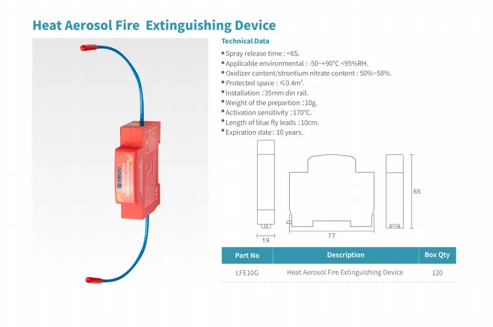
The compact DIN-rail heat aerosol fire extinguishing device shown above represents an engineered solution for localized, modular enclosure protection. Below is an engineering parameter breakdown based on standard technical ratings:
| Technical Parameter | Specification / Design Value |
|---|---|
| Model Designation | LFE10G Series (Compact Modular Fire Extinguishing Device) |
| Mounting Interface | Standard 35 mm DIN Rail Mount (EN 50022) |
| Physical Dimensions (L × H × W) | 77 mm × 65 mm × 19 mm (Matches standard single-pole modular switchgear width) |
| Solid Agent Mass (Preparation) | 10 grams |
| Extinguishing Compound Chemistry | Oxidizer content / Strontium Nitrate formulation: 50% ~ 58% |
| Effective Protected Space Volume | ≤ 0.4 m³ (Per individual modular unit) |
| Thermal Activation Sensitivity | 170°C (Direct thermal cord / fly lead trigger) |
| Thermal Fly Lead Length | 10 cm flexible dual-ended thermal detection cords |
| Spray Release Duration | < 6 Seconds (Ultra-fast total flooding kinetics) |
| Environmental Operating Envelope | −50°C to +90°C / Relative Humidity < 95% RH |
| Operational Service Life | 10 Years (Non-pressurized, zero routine pressure testing required) |
| Standard Packaging Quantity | 120 units per carton box |
Engineering Note: While single 10g units provide coverage for compact volumes (≤ 0.4 m³), larger distribution boards or compartmentalized switchgear lineups should be engineered using multiple synchronized or distributed modules positioned across individual busbar and cable termination compartments.
Which Cabinet Fire Protection Technologies Should Panel Builders Compare?
Heat-Activated Aerosol vs. Electrically Activated Aerosol Devices
Heat-Activated (Thermal Cord) Devices: Completely autonomous and non-electric. They rely on a specialized thermal cord or bulb that triggers chemical agent generation when exposed to direct flame or temperatures exceeding 170°C. They operate reliably without external power, batteries, or central fire alarm panels, making them fail-safe during total panel power outages.
Electrically Activated Aerosol Devices: Triggered via a low-voltage electrical pulse (e.g., 24V DC from a smoke detector, thermal sensor relay, or central building management system). This allows multi-criteria fire detection (earlier warning via optical smoke or aspirating sensors) but introduces wiring dependency and requires backed-up control power.
Aerosol vs. Gaseous Suppression Systems (CO2 / Novec 1230 / FM-200)
Clean agent gaseous systems store liquefied or compressed gas in heavy metal cylinders connected via distribution pipe networks, nozzles, and solenoid valves. While clean gases leave absolutely zero residue, they require substantial external floor space, continuous pressure monitoring, periodic cylinder hydrostatic testing, and complex mechanical piping. Compact solid-state aerosol devices generate agent on-demand from non-pressurized solid compounds, saving 90% of weight and space.
Automatic Fire Suppression vs. Fire Detection-Only Systems
A detection-only system (such as point smoke detectors or thermal linear heat cables connected to a panel sounder) only issues an alarm. In unattended electrical rooms or remote solar substations, detection without autonomous suppression leaves a 15-to-45-minute window for fire propagation before human firefighters arrive.
| Selection Factor | Heat-Activated Aerosol | Electrically Activated Aerosol | Gaseous Suppression (Clean Agent) |
|---|---|---|---|
| Activation Mechanism | Direct thermal sensing cord / bulb (Self-contained) | Electrical signal from external smoke/heat controller | Pneumatic or electrical solenoid actuator |
| Space & Form Factor | Ultra-compact (DIN-rail or panel wall bracket) | Compact generator + external detection module | Bulky (External cylinder rack + distribution pipework) |
| Power Dependency | 100% Autonomous (Zero electrical power required) | Requires 12V/24V DC auxiliary power backup | Requires panel/battery power for release module |
| Piping & Pressure | Zero piping; non-pressurized solid compound | Zero piping; non-pressurized solid compound | High-pressure storage cylinders (25 bar to 200 bar) |
| Post-Discharge Residue | Micro-fine dry non-conductive dust (Vacuum cleanable) | Micro-fine dry non-conductive dust (Vacuum cleanable) | Zero residue (Gas evaporates completely) |
| Maintenance Demands | Visual inspection only (10-year service life) | Loop continuity test + sensor calibration | Annual pressure checks, weighing, hydrostatic tests |
| Ideal Applications | Standard MCCs, control panels, PV combiner boxes | Critical data center racks, integrated BMS switchgear | Large walk-in switchgear rooms, server rooms |
How Should Panel Builders Verify Product Specifications Before Procurement?
Which Technical Documents Should Buyers Request?
- Complete Engineering Datasheet: Must explicitly state active chemical composition (strontium/potassium ratio), gross weight, agent weight, operating temperature, and certified protected volume.
- Mechanical Dimensional & Mounting Drawings (CAD/STEP): Outlining DIN-rail latch tolerances, minimum clearance distances, and thermal cord routing envelopes.
- Independent Fire Test Reports: Laboratory test results detailing fire extinguishment on Class A, B, and Electrical test cribs under standardized enclosure leakage rates.
- Dielectric & Insulation Resistance Test Certificates: Validating that aerosol residue does not cause flashovers across live terminals up to standard system voltages.
- Material Safety Data Sheet (MSDS / SDS): Detailing chemical toxicity, environmental impact (zero ODP, zero GWP), and post-discharge handling procedures.
- Service Life & End-of-Life Disposal Documentation: Guidelines for safe recycling and disposal after 10 years of service.
How Can Buyers Verify the Rated Protected Volume?
- Inquire whether the rated volume (e.g., 0.4 m³) is calculated based on hermetically sealed test boxes or accounts for realistic enclosure leakage (e.g., IP42 / IP54 industrial panels).
- Check the tested extinguishing density ($g/m^3$). For standard electrical cabinet fires, reliable aerosol concentrations typically range between $50\ g/m^3$ and $100\ g/m^3$.
What Should OEM Buyers Confirm with the Manufacturer?
- Quality Management Certifications: Ensure production under ISO 9001, ISO 14001, and ISO 45001 certified manufacturing facilities.
- Batch Traceability & Laser Serialization: Each device must have a permanent serial number indicating manufacture date, batch number, and expiration date.
- OEM / ODM Customization: Ability to provide customized thermal cord lengths, custom trigger temperatures (e.g., 140°C, 170°C, 200°C), feedback signal contacts (pressure switch or micro-switch feedback to PLC), or private labeling.
What Are the Most Common Cabinet Fire Protection Selection Mistakes?
Mistake 1: Sizing Strictly on Gross Geometric Dimensions Without Accounting for Enclosure Leakage
Engineering Risk:
Calculating panel volume purely as $L \times W \times H$ on a ventilated or unsealed enclosure leads to under-concentration. Extinguishing agent escapes through cooling louvers, allowing deep-seated electrical arcing fires to reignite.
Correct Verification Practice:
Calculate gross cabinet volume, deduct solid components, and apply a 1.2 to 1.3 safety compensation factor for enclosures with passive ventilation slots. For forced-ventilation cabinets, install interlocks that immediately shut down cooling fans upon thermal detection.
Mistake 2: Confusing Continuous Operating Temperature with Thermal Trigger Threshold
Engineering Risk:
Selecting a device with a 90°C thermal cord inside a drive panel that reaches 80°C under full summer load creates a severe risk of false discharge, causing unnecessary process shutdowns.
Correct Verification Practice:
Verify that the nominal trigger temperature (e.g., 170°C) is at least 50°C to 80°C above the highest localized operating temperature, while ensuring the environmental operating specification (−50°C to +90°C) comfortably envelopes ambient extremes.
Mistake 3: Overlooking Forced Ventilation and Cooling Airflow Paths
Engineering Risk:
If forced exhaust fans continue operating after a fire starts, the extinguishing aerosol cloud is sucked out of the cabinet within seconds, neutralizing its fire suppression capability.
Correct Verification Practice:
Incorporate a thermal cutoff switch or auxiliary contact on the fire protection device to cut power to enclosure cooling fans immediately upon thermal activation.
Mistake 4: Equating Rapid Discharge Time with Guaranteed Extinguishment
Engineering Risk:
A device that discharges in < 6 seconds only achieves agent distribution. If the agent density is insufficient or the cabinet is opened immediately, re-ignition can occur on red-hot copper busbars.
Correct Verification Practice:
Ensure the design provides adequate agent hold time (retention of extinguishing concentration for at least 10 minutes) and require personnel to keep cabinet doors closed post-discharge.
Mistake 5: Relying on Generic CE Marks Without Inspecting Actual Test Protocols
Engineering Risk:
Generic CE marks on industrial goods can refer merely to EMC or low-voltage safety directives rather than verified fire suppression efficacy testing.
Correct Verification Practice:
Request specific third-party test reports conducted in accordance with recognized fire suppression testing guidelines (such as ISO 15725 or NFPA 2010 protocols).
Mistake 6: Treating Fire Suppression as a Substitute for Circuit Breakers and Electrical Maintenance
Engineering Risk:
Treating fire protection as an excuse to relax electrical safety standards (e.g., improper wire gauge sizing, skipped torque inspections) can cause repetitive thermal events that degrade panel equipment.
Correct Verification Practice:
Maintain rigorous switchboard design practices (IEC 61439 compliance, thermal imaging inspections, calibrated torque audits). Fire suppression is an emergency defense layer, not a substitute for proper engineering.
Panel Builder’s Cabinet Fire Protection Selection Checklist
| Checkpoint | Engineering Verification Item | Status / Value |
|---|---|---|
| 1. Cabinet Net Volume | Calculate internal height × width × depth; identify interior partitions and separate isolated compartments. | [ ] Verified: ______ m³ |
| 2. Suppression Sizing | Confirm single or multiple device capacity exceeds total net volume (with 20% margin for ventilated cabinets). | [ ] Sizing Matched |
| 3. Thermal Profile | Verify activation rating (e.g., 170°C) provides sufficient thermal buffer above maximum operating temperature. | [ ] Thermal Headroom OK |
| 4. Mechanical Fit | Confirm 35 mm DIN rail or bracket space, depth clearance, and thermal lead routing path above high-risk terminals. | [ ] Space Allocated |
| 5. Discharge Clearance | Ensure minimum 50 mm clearance in front of discharge nozzle away from sensitive plastic components. | [ ] Clearance Verified |
| 6. Environmental Rating | Check ambient operating range (−50°C to +90°C) and moisture resistance (< 95% RH non-condensing). | [ ] Environment Passed |
| 7. Dielectric Safety | Verify test data showing non-conductive residue and insulation resistance compatibility with distribution voltages. | [ ] Non-Conductive Cert OK |
| 8. Standard Compliance | Examine third-party fire test reports covering Class A, B, C, and Electrical Fire (Class E) performance. | [ ] Test Reports Reviewed |
| 9. Service Lifecycle | Confirm shelf life (10 years maintenance-free) and inspect manufacturer serial numbering and batch tracking. | [ ] 10-Year Shelf Life Confirmed |
| 10. Supplier Reliability | Audit manufacturer ISO 9001 certification, warranty terms, and OEM customization capabilities. | [ ] Supplier Approved |
FAQ — Cabinet Fire Protection Devices
What is a cabinet fire protection device?
A cabinet fire protection device is a self-contained, compact automatic fire extinguisher installed directly inside electrical enclosures, switchboards, or control cabinets. It autonomously detects localized thermal buildup or flames and releases an extinguishing agent (such as solid-state micro-aerosol or clean gas) directly onto the fire source within seconds, preventing electrical panel destruction.
How do you choose a fire suppression device for an electrical cabinet?
To choose the correct device, calculate the internal net volume of the enclosure, check the normal operating and peak temperatures, assess enclosure ventilation/leakage, choose an installation method (such as 35 mm DIN rail), verify third-party fire test reports for electrical fires, ensure the residue is non-conductive, and confirm a maintenance-free service life.
What size aerosol fire suppression device does a control panel need?
The size depends on the enclosure’s internal volume and design application density. For example, a single compact 10g aerosol device (like model LFE10G) protects enclosed volumes up to 0.4 m³. For larger enclosures (e.g., a standard 2.0 m × 0.8 m × 0.6 m switchgear cabinet with a volume of ~0.96 m³), panel builders should install two to three 10g units or a single larger-capacity generator (e.g., 30g to 100g) to ensure proper coverage.
What is the difference between activation temperature and operating temperature?
Operating temperature is the ambient environmental temperature range in which the device can sit safely in stand-by mode without degrading (e.g., −50°C to +90°C). Activation temperature is the specific elevated temperature (e.g., 170°C) required to trigger the thermal cord or mechanical sensor and discharge the extinguishing agent.
Can a DIN-rail-mounted aerosol device protect a low-voltage distribution board?
Yes. DIN-rail aerosol devices are designed specifically for low-voltage distribution boards, MCCs, and automation panels. Because they clip directly onto standard 35 mm DIN rails alongside breakers and terminal blocks, they fit seamlessly without requiring external pipework or panel wall modifications.
Does aerosol fire suppression leave residue inside the cabinet?
Yes, solid-state aerosol devices produce a cloud of ultra-fine, dry mineral salts (typically strontium- or potassium-based). In certified electrical-grade formulations, this residue is dry, non-conductive, and non-corrosive. After a discharge event, the residue can be cleaned from electrical gear using an industrial vacuum equipped with a HEPA filter or blown out with dry compressed air.
Can a cabinet fire protection device replace a circuit breaker?
No. A fire protection device and a circuit breaker perform distinct, complementary safety functions. Circuit breakers interrupt overcurrents and dead short circuits. Fire suppression devices extinguish fires caused by high-resistance loose connections, component overheating, and arcing faults that draw normal operating current and fail to trip electrical breakers.
What technical documents should panel builders request from suppliers?
Panel builders should request the manufacturer’s product technical datasheet, 2D/3D CAD mounting drawings, third-party electrical fire test reports, dielectric insulation test records, Material Safety Data Sheets (MSDS), standard conformity certificates, and manufacturer warranty documentation.