Executive Summary for Electrical Engineers & Contractors: Low-voltage (LV) distribution boards, motor control centers (MCCs), and photovoltaic combiner panels house concentrated energized electrical assets where thermal faults can escalate rapidly. While traditional circuit breakers mitigate downstream overcurrents, they cannot eliminate micro-arcing or localized resistive heating fires. Condensed aerosol fire suppression systems provide compact, non-pressurized, total-flooding extinguishing directly inside the enclosure. This guide delivers actionable engineering methodologies for calculating extinguishing volume, sizing thermal/electrical actuators, ensuring electrical safety coexistence, and maintaining compliance across industrial panel assemblies.
Learn More: What Is a Heat-Activated Aerosol Fire Extinguishing Device?
Why Do Low-Voltage Distribution Boards Need Fire Protection?
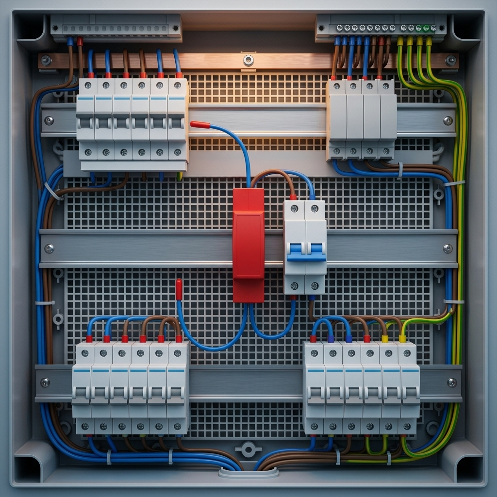
Low-voltage distribution boards are the primary nerve centers of commercial, industrial, and utility power distribution. When an internal fault occurs, the high energy density, combustible wire insulation, polymer housings, and localized heating create severe fire hazards capable of crippling plant operations within minutes.
What Are the Common Causes of Electrical Fires in Distribution Boards?
Electrical enclosure fires rarely occur without precursor anomalies. The primary ignition sources include:
- Loose Terminal Connections and Overheating: Cyclic mechanical vibrations, poor initial commissioning torque, and thermal expansion cause screw terminals and lugs to loosen. This elevates contact resistance, generating extreme localized I2R heat without tripping protective devices.
- Insulation Degradation: Continuous thermal stress, elevated ambient temperatures, ultraviolet exposure, or chemical attack cause PVC, XLPE, and composite insulation to become brittle, leading to dielectric breakdown.
- Short Circuits and Electrical Arcing: Transient overvoltages, component fatigue, or accidental tool contact can bridge phases or ground, triggering high-temperature plasma arcs that instantaneously ignite nearby plastics.
- Overloaded Circuits: Sustained operational overloads running near breaker thresholds increase steady-state operating temperatures, accelerating thermal aging of conductor sleeves and switch bodies.
- Dust, Moisture, and Environmental Contamination: Ingress of conductive airborne particulate matter, high humidity, or chemical vapors causes surface tracking and dielectric flashovers across busbar insulating barriers.
Which Components in a Distribution Board Are Most Vulnerable to Fire?
Fire risk within an LV switchboard concentrates around points of mechanical termination, switching contact points, and auxiliary electronics:
- Circuit Breakers and Terminal Connections: Molded Case Circuit Breakers (MCCBs) and Miniature Circuit Breakers (MCBs) undergo mechanical switching wear. Internal contact erosion and loose screw terminals represent the most frequent ignition origins. Reviewing breaker overheating and loose connection issues is vital to switchgear reliability.
- Busbars and Cable Terminations: High current densities at busbar fishplates, bolted splice joints, and incoming cable lugs create extreme thermal stresses if joint torque relaxes.
- Internal Wiring and Insulation: High-density control looms, jumper cables, and plastic cable trunking provide combustible fuel that spreads flames vertically across compartments.
- Control Components and Auxiliary Devices: Programmable Logic Controllers (PLCs), 24VDC switch-mode power supplies, contactor coils, and surge protective devices (SPDs) can suffer catastrophic internal component failure under prolonged overvoltage.
Can a Circuit Breaker Prevent Every Electrical Cabinet Fire?
A circuit breaker is designed to interrupt specified overcurrent and short-circuit conditions based on thermal and magnetic trip curves; however, it cannot detect every thermal hazard. High-resistance connections (glowing connections) draw current well within normal design parameters, meaning an MCCB or MCB will remain closed while the joint reaches temperatures above 600°C—igniting adjacent plastics.
Key Takeaway for Panel Builders & Specifiers: Circuit breakers protect electrical circuits against specified overcurrent and short-circuit conditions, but they do not eliminate every ignition risk. Fire suppression provides an essential, complementary layer of defense designed to detect and extinguish flames within the physical enclosure before fire propagates to adjacent plant equipment.
How Does Aerosol Fire Suppression Work in Low-Voltage Distribution Boards?
Condensed aerosol fire extinguishing systems deploy solid chemical compounds that, upon activation, undergo an exothermic reaction to generate ultra-fine potassium-based micro-particles (principally K2CO3) suspended in an inert gas matrix (N2, CO2).
What Happens When an Aerosol Fire Suppression Device Activates?
The suppression sequence inside an electrical enclosure proceeds rapidly through distinct mechanical and chemical phases:
- Initiation: The device is triggered either autonomously via a calibrated thermal cord/bulb (e.g., at 170°C) or electrically via an auxiliary fire control panel or smoke detection loop.
- Aerosol Generation: The solid aerosol-forming compound inside the canister reacts without requiring high-pressure storage cylinders, converting into micron-sized aerosol particles.
- Discharge & Flooding: The aerosol gas stream discharges through engineered nozzles, dispersing throughout the enclosed cabinet in 5 to 15 seconds.
- Chemical Flame Inhibition: Unlike water (which cools) or CO2 (which displaces oxygen), potassium radicals (K•) react directly with combustion free radicals (H• and OH•) to form stable potassium hydroxide (KOH), breaking the combustion chain reaction at a molecular level without depleting oxygen below life-support thresholds.
Where Should an Aerosol Fire Suppression Device Be Installed?
Correct spatial positioning ensures uniform total-flooding coverage without thermal interference:
- Mount units inside sealed or semi-sealed enclosures rated IP22 to IP65, ideally on the upper sidewalls or ceiling where hot convection plumes gather.
- Locate the device near primary hazard zones (e.g., above main incoming MCCBs or busbar compartments) while maintaining manufacturer-specified clearance distances from combustible cables.
- Ensure the discharge path is completely unobstructed by cable trays, phase dividers, or large contactors to prevent premature particle impingement.
- Maintain accessibility for visual inspection of thermal leads and electrical actuators during scheduled panel maintenance.
What Is the Difference Between Standalone Aerosol Devices and Centralized Fire Suppression Systems?
Standalone units operate autonomously without external piping, pressure gauges, or electrical control loops, utilizing direct thermal actuation. Centralized systems route clean agent gases from external pressurized cylinder banks through a network of distribution pipes and solenoid valves triggered by room-level smoke detectors. Standalone condensed aerosols provide targeted, compartment-level protection with minimal architectural disruption.
Which Types of Low-Voltage Distribution Boards Can Use Aerosol Fire Suppression?
Condensed aerosol systems adapt across diverse enclosure formats, provided the compartment envelope can maintain the required agent concentration during the holding period.
Aerosol Fire Suppression for Main Distribution Boards
Main Low-Voltage Switchboards (MLVS / Form 4 assemblies) handle incoming supply currents from 800A to 6300A. Compartmentalization isolates busbar chambers, cable terminations, and incoming Air Circuit Breakers (ACBs). Installing dedicated compact aerosol units within individual Form 4 cubicles ensures localized extinguishment without taking down the entire switchboard lineup.
Aerosol Fire Suppression for Sub-Distribution Boards
Wall-mounted sub-distribution panels feeding commercial lighting, HVAC, and branch circuits feature compact footprints. Ultra-compact aerosol generators (ranging from 20g to 100g of chemical mass) mount easily to inner cabinet walls or top plates without occupying DIN-rail space or exceeding enclosure depth limitations.
Aerosol Fire Suppression for Motor Control Centers (MCCs)
MCC buckets contain contactors, thermal overloads, soft starters, and Variable Frequency Drives (VFDs). VFD internal capacitors and power semiconductors generate continuous heat. Standalone aerosol canisters inside individual drawout compartments extinguish component failures before toxic fumes or fires cross over to adjacent motor feeder cells.
Aerosol Fire Suppression for Solar PV and EV Distribution Equipment
Photovoltaic combiner boxes, DC-to-AC inverters, and EV charging distribution pillars face severe ambient swings, moisture exposure, and continuous high-load thermal cycling. Applying tailored aerosol units with appropriate solar PV breaker selection protocols safeguards outdoor-rated IP65 enclosures against persistent DC arcs and thermal runaway conditions.
How Do You Select an Aerosol Fire Suppression Device for a Distribution Board?
Engineering a reliable fire suppression installation requires rigorous calculation of enclosure volume, verification of thermal dynamics, and alignment with industrial testing standards.
How Do You Calculate the Required Protected Volume?
Calculate the gross internal geometric volume of the electrical enclosure before considering agent mass requirements:
V = L × W × H
Where V is the gross internal volume in cubic meters (m3), and L, W, and H are the internal length, width, and height in meters. The required aerosol compound mass (M in grams) is calculated using the design application density (q in g/m3) supplied by the manufacturer under ISO 15727 or NFPA 2010 testing:
M = V × q × fadd
Where fadd is a safety design factor (typically 1.15 to 1.30) that accounts for ventilation openings and unsealed wire penetrations.
| Enclosure Type | Dimensions (H × W × D) | Gross Volume (V) | Typical Design Density (q) | Recommended Solid Mass |
|---|---|---|---|---|
| Wall-Mount Sub-Panel | 0.8m × 0.6m × 0.25m | 0.12 m3 | 100 g/m3 | ~15–20 g Unit |
| Floor-Standing Panelboard | 1.8m × 0.8m × 0.4m | 0.576 m3 | 100 g/m3 | ~60–100 g Unit |
| Standard MCC Column | 2.2m × 0.8m × 0.6m | 1.056 m3 | 100 g/m3 | ~120–150 g Unit |
| Main Switchboard Section | 2.2m × 1.2m × 0.8m | 2.112 m3 | 100 g/m3 | ~250–300 g Unit |
How Does Activation Temperature Affect Device Selection?
Distinguish between maximum continuous ambient operating temperature and thermal activation threshold:
- Maximum Panel Operating Temperature: Enclosures housing high-density breakers or VFDs routinely reach 50°C to 70°C under full load. The selected suppression unit’s casing must be rated for sustained ambient conditions up to 85°C or higher.
- Activation Temperature: Thermal activation cords or sensing heads should be rated at 170°C to 200°C. This margin prevents nuisance activation during temporary busbar overloads while ensuring instantaneous triggering when exposed to open flames or severe micro-arcing.
How Do Cabinet Layout and Aerosol Discharge Affect Installation?
High component density affects agent dispersion. If an enclosure features horizontal separation plates or Form 2/3/4 barriers, aerosol cannot freely pass between tiers. In compartmentalized boards, each isolated chamber requires its own dedicated aerosol unit sized for that sub-volume. Discharge nozzles must point away from sensitive relay displays to prevent direct thermal impingement during release.
What Technical Specifications Should Panel Builders Check?
| Specification Parameter | Recommended Engineering Criteria | Standard Verification |
|---|---|---|
| Coverage Rating | Certified design concentration (e.g., 50–100 g/m3) | ISO 15727 / NFPA 2010 / UL 2775 |
| Activation Mode | Thermal cord (170°C), electric pulse (24VDC, ≥1A), or dual | Factory Test Reports |
| Discharge Time | Rapid total flooding within 5 to 15 seconds | Discharge Test Certificate |
| Operating Ambient Limits | -40°C to +85°C; Relative Humidity up to 95% non-condensing | Environmental Climatic Tests |
| Dielectric Clearance | Non-conductive discharge stream up to 24kV | Dielectric Withstand Testing |
| Design Service Life | Minimum 5 to 10 years maintenance-free lifespan | Accelerated Aging Reports |
Aerosol Fire Suppression vs Other Fire Protection Methods
Selecting fire protection for electrical panels requires evaluating space constraints, maintenance overhead, extinguishing speed, and equipment impact.
Aerosol vs Gas Fire Suppression for Electrical Distribution Boards
Gaseous clean agents (such as FM-200, Novec 1230 / FK-5-1-12, or Inergen) are effective total-flooding solutions for entire switchgear rooms. However, deploying them inside individual cabinet volumes requires extensive high-pressure piping, directional nozzles, cylinder storage footprints, and continuous room overpressure relief vents. Condensed aerosols eliminate pressurized cylinders and pipework entirely, operating as self-contained micro-extinguishers inside each cabinet.
Aerosol Fire Suppression vs Conventional Fire Extinguishers
Portable CO2 or dry chemical extinguishers depend on human intervention. Electrical fires often ignite when facilities are unoccupied or propagate behind locked enclosure doors. Opening a burning panel door introduces fresh oxygen, which can cause an explosive flashover. Standalone aerosol devices provide immediate, automatic suppression inside the closed cabinet without human risk.
Aerosol Fire Suppression vs Fire Detection and Alarm Systems
Aspirating Smoke Detectors (ASD) and standard optical smoke sensors provide early warning, sounding alarms or signaling SCADA networks. However, detection alone cannot extinguish a fire. Modern electrical protection strategies pair aerosol suppression with dry contact feedback modules, enabling the unit to report activation directly to central Building Management Systems (BMS).
| Protection Method | Primary Function | Main Consideration | Cabinet Footprint Impact |
|---|---|---|---|
| Circuit Breaker (MCB/MCCB) | Interrupt specified overcurrent & short-circuit conditions | Proper rating, trip curve, and coordination | Standard panel component |
| Fire Detection System | Detect combustion particles and initiate alarms | Sensor placement and system latency | Requires external cabling/relays |
| Condensed Aerosol System | Suppress flaming fires via potassium radical chemistry | Correct volume calculation and compartment sealing | Compact, unpressurized interior mount |
| Portable Extinguisher | Manual, human-operated firefighting response | Operator availability and flashover hazards | External wall mount outside panel |
What Are the Limitations of Aerosol Fire Suppression in Distribution Boards?
While condensed aerosol systems are highly effective, electrical engineers must evaluate their specific operational limitations during project design.
Can Aerosol Residue Affect Electrical Components?
Aerosol discharge releases fine potassium carbonate particles. In dry conditions, this residue is non-conductive and inert. However, if exposed to excessive humidity or water ingress, potassium salts can exhibit slight hygroscopic conductivity. Following an activation event, maintenance teams must de-energize the panel, vacuum away settled dust with HEPA filtration, and wipe contact terminals with approved electrical solvent cleaners before re-commissioning.
Is Aerosol Fire Suppression Suitable for Every Electrical Fire?
Aerosol suppression is optimized for Class A (combustible wiring, structure), Class B (flammable solvents), Class C (energized electrical gear), and electrical fire scenarios. However, it cannot extinguish chemical oxidizers or Class D metal fires. In battery energy storage system (BESS) panels containing lithium-ion cells, aerosols suppress open flames but cannot halt internal short-circuit thermal runaway without auxiliary cell cooling.
Does an Aerosol Device Replace Circuit Breakers or Fire Alarms?
No. Aerosol suppression functions strictly as a physical fire extinguishing layer. It cannot interrupt upstream electrical faults. Upstream protection must remain governed by properly coordinated types of low-voltage circuit breakers and residual current devices (RCCBs/RCDs) adhering to IEC 60947 and IEC 60364 installation codes.
What Are the Common Installation Mistakes to Avoid?
- Choosing a Device Without Verifying the Protected Volume: Sizing based on visual estimates rather than true geometric dimensions results in under-dosing, preventing the aerosol from achieving its critical extinguishing concentration.
- Installing the Device Where Aerosol Discharge Is Obstructed: Mounting a unit directly behind thick cable bundles or solid steel mounting plates blocks the discharge plume, preventing rapid gas expansion.
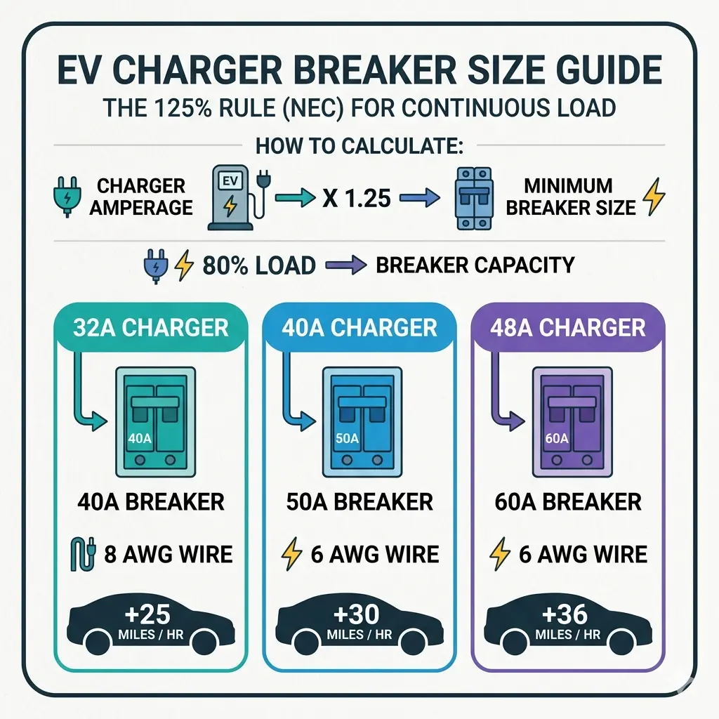
- Ignoring Normal Operating Temperatures: Placing a thermally activated generator too close to heat sinks, high-wattage power supplies, or uninsulated exhaust vents risks false activation under normal peak loads. Refer to guidelines on proper breaker sizing for continuous loads to evaluate internal cabinet heat.
- Overlooking Enclosure Openings and Ventilation: Leaving large unsealed louvered panels or open floor cable glands allows the extinguishing agent to escape before complete knockdown. Install automatic ventilation dampers or account for leakage with higher dosing factors.
- Failing to Verify Certification and Manufacturer Instructions: Installing uncertified fire suppression devices lacking third-party ISO/NFPA/UL validation can void facility insurance and panel type-test compliance.
- Treating Fire Suppression as a Substitute for Electrical Maintenance: Fire suppression does not replace regular infrared thermographic inspections, bolt torque verification, and breaker testing.
How Should Aerosol Fire Suppression Devices Be Inspected and Maintained?
Because condensed aerosol units operate without pressure gauges or pressurized gas cylinders, maintenance requirements are streamlined compared to conventional gas flooding systems.
What Should Be Checked During Routine Inspections?
Incorporate the following checks into quarterly or semi-annual panel maintenance schedules:
- Visual Integrity: Ensure the canister body shows no physical denting, corrosion, or seal degradation.
- Mounting Security: Confirm mounting brackets and vibration-damping clamps are securely fastened.
- Actuation Path: Inspect the thermal detection line or electrical wiring for physical wear, chafing, or thermal discoloration.
- Discharge Clearance: Verify that no newly installed cables or relays obstruct the nozzle discharge clearance zone.
When Should an Aerosol Fire Suppression Device Be Replaced?
Aerosol devices must be replaced immediately after an activation event. For unactivated devices, replace the unit upon reaching its certified operational service lifespan (typically 5 to 10 years from the manufacturing date, as stamped on the nameplate).
What Documentation Should Maintenance Teams Keep?
Maintain an on-site log containing: unit model number and serial numbers, cabinet identification code, installation date, certified expiration date, commissioning technician signature, and chronological visual inspection records.
FAQ — Aerosol Fire Suppression for Low-Voltage Distribution Boards
Can Aerosol Fire Suppression Be Installed Inside a Distribution Board?
Yes. Standalone condensed aerosol generators are engineered specifically for direct installation inside low-voltage switchboards, MCCs, and control cabinets. Their compact, unpressurized design allows them to mount securely on enclosure walls or ceilings.
Does a Low-Voltage Distribution Board Need a Separate Fire Suppression System?
While broad building codes may only mandate room-level sprinkler or detection systems, localized in-cabinet suppression provides essential protection. Water sprinklers cannot activate until flames breach the panel enclosure—at which point the switchboard is destroyed and water causes extensive collateral electrical damage.
How Do You Calculate the Required Aerosol Suppression Capacity?
Measure the gross internal cabinet volume (Length × Width × Height in meters) and multiply it by the manufacturer’s certified extinguishing design density (typically 70–140 g/m3 depending on the agent and enclosure leakage factor).
Can Aerosol Fire Suppression Damage Circuit Breakers or Electronic Components?
No. When properly specified, aerosol discharge does not cause thermal shock or mechanical damage to breakers, busbars, or relays. The residue is non-corrosive in dry environments and can be cleaned using HEPA vacuuming and standard solvent wipes.
What Is the Difference Between Aerosol Suppression and a Fire Alarm?
A fire alarm is an early detection and signaling mechanism that alerts personnel or trips supervisory relays. An aerosol fire suppression device physically discharges an active chemical extinguishing agent to extinguish open flames.
Can Aerosol Fire Suppression Replace an RCCB, MCB, or MCCB?
No. An aerosol unit cannot clear overloads, ground faults, or short circuits. It serves exclusively as a fire safety barrier, working alongside standard circuit breakers conforming to national electrical codes.
How Often Should an Electrical Cabinet Aerosol Device Be Inspected?
Visual inspections should be conducted every 6 to 12 months alongside routine switchboard maintenance. The system requires no pressure checks, weighing, or hydrostatic cylinder testing throughout its operational lifespan.