For electricians, panel builders, and facility managers, accurately interpreting electrical drawings is fundamental to safe and compliant installations. At the core of these schematics is the low voltage circuit breaker symbol. Understanding the circuit breaker symbol meaning is crucial for specifying the right components, troubleshooting industrial systems, and ensuring proper circuit protection.
Whether you are an OEM engineer designing control panels or a B2B distributor sourcing components, knowing how to read electrical diagram symbols for breakers will streamline your workflow and prevent costly errors.
Quick Answer: What Does a Circuit Breaker Symbol Mean?
When you encounter electrical drawings, you need to extract information quickly and accurately.
A low voltage circuit breaker symbol represents a protective device used in electrical diagrams to interrupt current during faults. It is typically labeled with a reference designator (e.g., CB1) and annotated with key specifications such as current rating, voltage, trip curve, and breaking capacity.
What Is a Low Voltage Circuit Breaker Symbol?
Why Circuit Breaker Symbols Are Used in Electrical Diagrams
Electrical schematics are universal languages used by engineers and technicians worldwide. Circuit breaker symbols provide a standardized way to represent protection devices in single-line diagrams and schematic drawings. Instead of drawing complex mechanical internals, these symbols convey the functional role of the breaker, ensuring clarity and consistency across complex power distribution networks.
Where Are Breaker Symbols Commonly Found?
You will typically encounter these symbols in various technical documents:
- Single-line diagrams (SLD): Showing the overall power distribution flow from the main feed down to sub-panels.
- Distribution layouts: Detailing how switchgear and panelboards are organized.
- Control schematics: Illustrating the logic and protection circuits for machinery and automation systems.
How to Identify a Circuit Breaker in a Diagram
Reference Designator (CB1, CB2, etc.)
In standard schematics, letters are used to categorize components. The abbreviation “CB” universally stands for circuit breaker. For example, a label reading “CB1” simply means Circuit Breaker 1. Each breaker symbol should include a reference label to provide clear identification within the system. This prevents confusion when cross-referencing a diagram with a physical panel layout or a Bill of Materials (BOM).
Breaker Type Abbreviations
Beyond the basic symbol, specific abbreviations denote the exact type of breaker required for the application. Here are the most common ones encountered by industrial buyers and electricians:
| Abbreviation | Full Name | Typical Application |
|---|---|---|
| MCB | Miniature Circuit Breaker | Final distribution, lighting, and small motor protection. |
| MCCB | Molded Case Circuit Breaker | Higher current ratings, main feeders, industrial panels. |
| RCCB / RCD | Residual Current Device / Circuit Breaker | Protection against earth leakage and electrical shock. |
| GFCI | Ground Fault Circuit Interrupter | North American equivalent to RCCB, common in wet areas. |
What Technical Ratings Are Shown on Circuit Breaker Symbols?
Current Rating (Amperage)
The symbol is usually accompanied by a number representing its nominal current rating, such as 20A. This value indicates the maximum continuous current the breaker can carry without tripping under normal operating conditions.
Voltage Rating
The voltage rating must match the system voltage to ensure safe arc extinction during a fault. Common annotations include 230V for single-phase or 400V for three-phase systems.
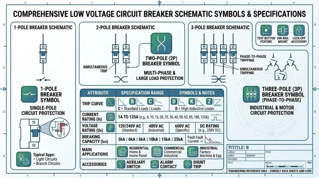
Trip Curve (B, C, D Types)
The tripping characteristics are crucial for handling inrush currents without nuisance tripping. Trip curve letters define how quickly a breaker responds to overcurrent conditions.
- Type B: Trips at 3 to 5 times rated current; ideal for residential lighting and resistive loads.
- Type C: Trips at 5 to 10 times rated current; standard for commercial applications, motors, and HVAC systems.
- Type D: Trips at 10 to 20 times rated current; designed for industrial equipment with very high inrush currents, like transformers and large welders.
Breaking Capacity (Short-Circuit Rating)
This value, often denoted in kiloamps (e.g., 6kA or 10kA), specifies the maximum fault current the breaker can safely interrupt without being destroyed.
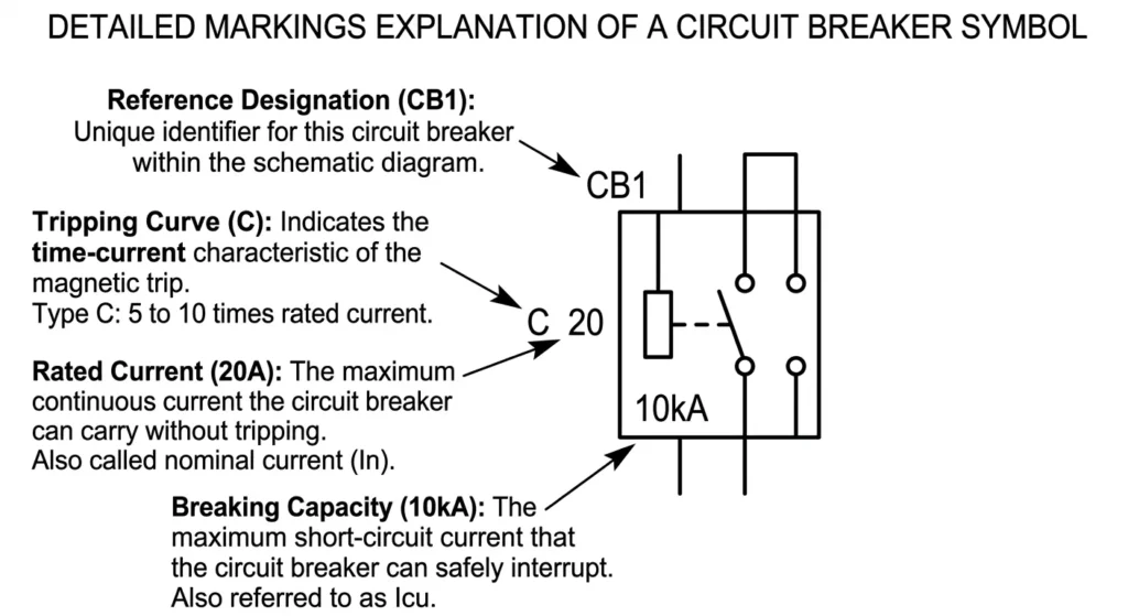
Example of a Breaker Label (C20 Explanation)
When reading an electrical diagram, you often see alphanumeric codes next to the symbol. A label such as “C20” means a Type C breaker with a 20A current rating.
| Label Annotation | Meaning | How to Read It |
|---|---|---|
| C | Trip Curve | Type C (trips at 5-10x rated current). |
| 20 | Current Rating | 20 Amps maximum continuous load. |
| 10kA | Breaking Capacity | Can safely clear a 10,000 Amp short circuit. |
How Pole Configuration Is Represented in Breaker Symbols
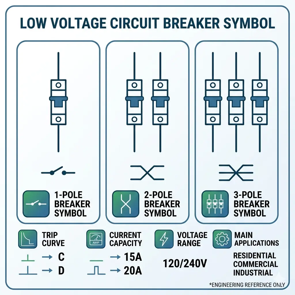
Number of Poles
The graphical symbol will duplicate the contact line to show the number of poles.
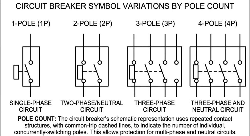
- 1P: Single-phase protection (live wire only).
- 2P: Split-phase or line + neutral applications.
- 3P: Three-phase motor or feeder protection.
- 4P: Three-phase + neutral protection.
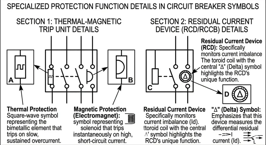
Protection Features in Symbols
Standard symbols often include small internal graphical elements. Additional markings may indicate protection types such as thermal-magnetic or differential (leakage) protection. A square wave shape might indicate thermal protection, while a half-circle can indicate magnetic protection.
Special Symbols for Leakage Protection
When dealing with life-safety devices like RCCBs or RCDs, look for the delta symbol. The “Δ” symbol indicates leakage or differential protection, highlighting that the device monitors the imbalance between live and neutral currents.
Additional Symbol Features in Circuit Breakers
Draw-Out vs Fixed Breaker Symbols
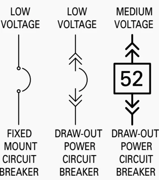
In heavy industrial switchgear (like Air Circuit Breakers – ACBs), symbols indicate mounting types. A fixed breaker uses a standard symbol, while a draw-out (withdrawable) breaker symbol includes specific arrows indicating plug-in capability for easier maintenance.
Isolation Function Indication
Not all breakers are rated for safe isolation. A horizontal dash may indicate that the breaker also functions as an isolator, meaning it guarantees complete physical separation of contacts when in the OFF position, allowing for safe downstream maintenance.
Operational Status Indicators
Advanced schematics may include auxiliary contacts linked to the main symbol, indicating open/closed status or signaling a tripped condition back to a PLC or SCADA system.
IEC vs ANSI: What Standards Define Circuit Breaker Symbols?
The appearance of the low voltage circuit breaker symbol varies depending on geographic location and the engineering standard applied.
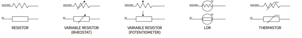
IEC 60617 Standard
Widely used in Europe and Asia, the IEC standard relies on precise, geometric graphical variations to depict specific functions (e.g., distinct shapes for thermal vs. magnetic trips).
ANSI / IEEE 315 Standard
Predominant in North America, the ANSI standard often utilizes simpler graphical forms (like a distinct curved line or zig-zag for breakers) and relies heavily on text annotations for detailed specifications.
Which Standard Should You Use?
Consistency is critical—use either IEC or ANSI standards throughout the entire project. Mixing standards within the same schematic can lead to severe misinterpretation during panel assembly or procurement.
| Feature | IEC 60617 | ANSI / IEEE 315 |
|---|---|---|
| Primary Region | Europe, Asia, Global | North America |
| Visual Style | Geometric, detailed functional shapes | Simplified lines, zig-zags |
| Information Density | Encoded in graphic details | Relies more on text annotations |
Best Practices for Labeling Circuit Breaker Symbols
Keep Labeling Consistent
Whether you are drafting or reading diagrams, maintain a strict naming convention. Do not mix “CB1” with “Q1” (another common designator for switching devices) unless explicitly defined in the legend.
Place Annotations Close to Symbols
To avoid reading errors on dense drawings, layout matters. Technical details should be placed adjacent to the symbol to prevent misinterpretation. If a C20 label is floating too far from the breaker symbol, a panel builder might assign it to the wrong circuit.
Verify with Manufacturer Data
Always cross-reference the diagram symbols and labels with the manufacturer’s documentation, including the specific datasheet and technical manuals, to ensure the physical component matches the engineered intent.
Common Mistakes When Reading Circuit Breaker Symbols
Misinterpreting Trip Curves
Applying a Type B breaker to a motor load (which requires a Type C or D) will result in nuisance tripping during startup, causing downtime and frustration.
Ignoring Breaking Capacity
Failing to read the short-circuit rating (e.g., installing a 6kA breaker where a 10kA fault is possible) is a massive safety hazard that can lead to electrical fires or explosive failures.
Confusing RCCB and MCB Symbols
Assuming an RCCB provides overcurrent protection is a dangerous error. Unless the symbol specifically denotes an RCBO (which combines both functions), an RCCB only protects against leakage, leaving the circuit vulnerable to overloads.
FAQ: Circuit Breaker Symbols Explained
What does a circuit breaker symbol mean?
It represents a protective device used to interrupt electrical current during faults.
What does “C20” mean on a circuit breaker?
It indicates a Type C breaker rated at 20A.
What is the difference between MCB and RCCB symbols?
MCB protects against overcurrent, while RCCB protects against leakage current.
What standard is used for electrical symbols?
IEC 60617 and ANSI/IEEE 315 are the most common standards.
What does the Δ symbol mean?
It indicates leakage or differential protection.
Conclusion: How to Read Circuit Breaker Symbols Correctly
Mastering electrical diagram symbols for breakers is an essential skill for modern electrical professionals. Remember that a complete understanding requires looking at three elements: the base graphical shape, the text annotations (like CB1 or C20), and the specific parameters regarding poles and protection types.
Understanding circuit breaker symbols requires combining graphical representation with technical annotations and standardized labeling systems.
For B2B buyers, facility managers, and OEM engineers, accurate interpretation directly impacts project safety and budget. Always take the time to verify symbol conventions, cross-check ratings, and ensure strict compliance with regional standards (IEC or ANSI) before specifying products or approving panel designs.