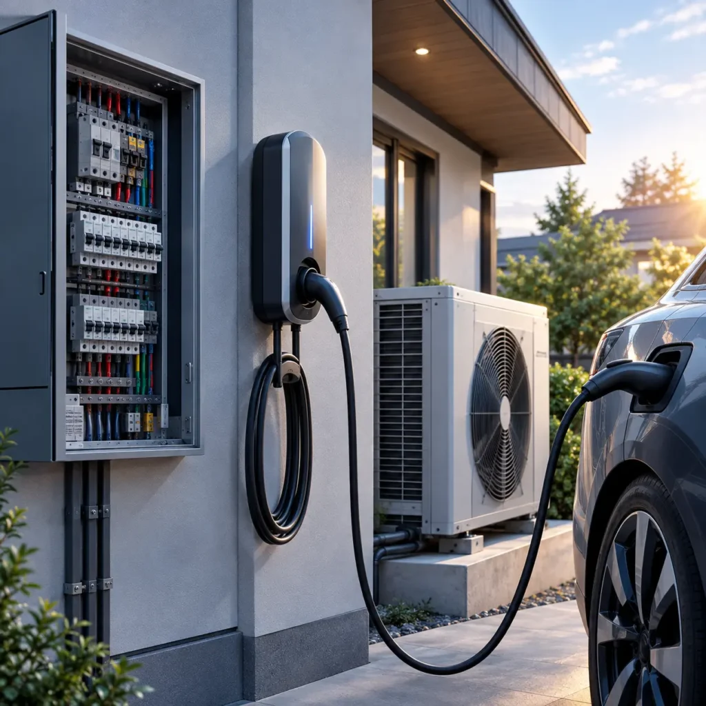
The global transition toward residential electrification has shifted the electrical load profile of modern dwellings. Where a domestic consumer unit once served intermittent, diversified resistive and small inductive loads (cooking, lighting, washing), it is now frequently tasked with supporting continuous, high-draw inductive and power-electronic loads. The two most significant additions are Electric Vehicle Supply Equipment (EVSE) and Air-to-Water / Air-to-Air Heat Pumps (ASHPs).
For electrical contractors, residential installers, and HVAC technicians, executing a dual EV charger and heat pump upgrade requires precise engineering. Standard rules of thumb no longer apply when high continuous current, non-linear harmonic distortion, DC residual fault leakage, and motor-starting inrush currents occur simultaneously. Sizing circuit protection and conductors incorrectly risks thermal fatigue, nuisance tripping, irreversible insulation breakdown, regulatory non-compliance, and severe fire hazards.
This technical guide details the comprehensive calculation methodology for determining Miniature Circuit Breaker (MCB) ratings and conductor cross-sectional areas (mm² or AWG) for dual-load residential upgrades across BS 7671, IEC 60364, and NEC frameworks.
Why Do EV Chargers and Heat Pumps Need Proper MCB and Cable Sizing?
Circuit protection and conductor selection are interlinked engineering decisions. Under fundamental electrical principles, protective devices exist primarily to protect the fixed wiring from overcurrent (thermal overload) and short-circuit faults, while maintaining service continuity under standard operating dynamics.
What Happens If an MCB Is Too Small for an EV Charger or Heat Pump?
- Nuisance Tripping Under Continuous Duty: An EV charger operates at maximum continuous rated capacity for 4 to 10 hours uninterrupted. Standard thermal-magnetic MCBs operating above 80% of nominal rating in high ambient enclosure temperatures experience bimetallic strip fatigue, leading to premature thermal tripping during normal charging.
- Inrush / Starting Current Mismatch: While modern heat pumps utilize variable-speed inverter-driven DC scroll compressors with low starting current (Soft Start), older or auxiliary booster units draw significant Locked Rotor Amps (LRA) or inductive inrush. An undersized MCB or an improper trip curve (e.g., Type B instead of Type C) will trip instantly on compressor start or when auxiliary defrost heaters engage.
- Reduced Circuit Availability & Component Wear: Repeated thermal-magnetic tripping accelerates internal contact oxidation, alters calibration characteristics, and disrupts critical building heating and vehicle mobility.
What Happens If the Cable Is Undersized?
- Excessive Conductor Temperature and I²R Losses: Power loss in a conductor is proportional to the square of the current ($P = I^2 R$). Continuous high current through an undersized cross-section generates severe thermal build-up, degrading PVC insulation ($70^\circ\text{C}$ limit) or XLPE insulation ($90^\circ\text{C}$ limit).
- Voltage Drop and Operational Instability: Long cable runs with inadequate copper cross-section cause terminal voltage to plummet. EV chargers may drop current or drop into fault mode when voltage falls below utility tolerances (e.g., <216V on a 230V nominal supply). Heat pump compressors run less efficiently, draw higher current to compensate for voltage drop, and risk electronic control board brownout.
- Insulation Degradation and Fire Risks: Sustained over-temperature leads to plasticizer migration, brittleness, and insulation breakdown, presenting latent phase-to-earth or phase-to-neutral arc fault and fire hazards within thermal insulation voids and service ducts.
- Terminal Overheating: High conductor temperatures transfer directly into MCB and equipment terminal lugs; review our guide on preventing overheating and loose connection issues to avoid terminal loosening through thermal expansion cycling.
Can an Existing Household Circuit Support Both an EV Charger and a Heat Pump?
No. Standard domestic final circuits (such as 32A ring final circuits or radial power circuits) cannot support an EV charger and a heat pump. Both appliances represent substantial loads requiring dedicated, individual radial circuits wired directly back to the distribution board or consumer unit.
Furthermore, standard diversity factors (which assume not all domestic appliances operate simultaneously) cannot be applied to EV chargers, and can only be minimally applied to heat pumps during extreme cold weather when auxiliary immersion elements and defrost cycles run concurrently with peak vehicle charging.
Core Engineering Principle: An MCB and cable must be calculated together based on design load current ($I_b$), installation routing, thermal de-rating factors, prospective fault current ($I_{pf}$), and earth fault loop impedance ($Z_s$). An undersized breaker trips unnecessarily; an oversized breaker allows the conductor to exceed its thermal limit before tripping, creating an acute structural fire hazard.
How Much Current Do EV Chargers and Heat Pumps Require?
Accurate circuit sizing begins with understanding the distinct electrical load profiles of EVSE and heat pump systems. Nameplate output power must never be confused with actual input electrical demand.
What Is the Typical Current Draw of a Home EV Charger?
EV chargers are pure continuous electrical loads classified under international standards (such as IEC 61851 and NEC Article 625) as operating at 100% rated current for 3 hours or more.
- Single-Phase 7.4 kW (Nominal 230V / 240V): Draws a steady-state current of 32A ($7,360\text{W} / 230\text{V} = 32\text{A}$).
- Single-Phase 3.6 kW (Nominal 230V): Draws a steady-state current of 16A ($3,680\text{W} / 230\text{V} = 16\text{A}$).
- Three-Phase 11 kW (Nominal 400V 3-phase): Draws 16A per phase ($11,000\text{W} / (\sqrt{3} \times 400\text{V} \times 1.0) \approx 15.9\text{A}$).
- Three-Phase 22 kW (Nominal 400V 3-phase): Draws 32A per phase ($22,000\text{W} / (\sqrt{3} \times 400\text{V} \times 1.0) \approx 31.8\text{A}$).
How Much Current Does a Residential Heat Pump Draw?
Heat pump sizing is complex because thermal heating capacity (kWth) is distinct from electrical input power (kWe) via the Coefficient of Performance (COP). An 8 kWth heat pump with a COP of 3.2 requires approximately 2.5 kWe of electrical power during steady-state compressor operation. However, electrical sizing must be based on Maximum Operating Current (MOC) and Minimum Circuit Ampacity (MCA), not average running current.
- Inverter-Driven Compressors: Soft-start electronics ramp current linearly, keeping starting inrush below 10A–15A. Nominal running current ranges from 8A to 16A for a 5 kW–12 kW thermal capacity system.
- Direct-On-Line (DOL) / Non-Inverter Compressors: Locked Rotor Amps (LRA) can reach 4 to 6 times Full Load Amps (FLA) for 200–500 milliseconds upon startup.
- Auxiliary / Back-up Immersion Heaters: Many heat pump indoor units include direct-acting resistive heating elements (3 kW, 6 kW, or 9 kW) configured to engage when ambient outdoor temperatures fall below the heat pump’s balance point, or during active reverse-cycle defrost. A 3 kW single-phase booster adds 13A of pure resistive load to the compressor’s running current.
What Happens When an EV Charger and Heat Pump Run at the Same Time?
During a cold winter night (sub-zero ambient temperature), a domestic dwelling experiences peak concurrent demand:
- EV Charger running at maximum rate: 32A
- Heat pump compressor running at full capacity: 14A
- Heat pump auxiliary defrost / immersion booster active: 13A
- Dwelling baseline background load (refrigeration, electronics, lighting): 5A to 10A
- Total Combined Instantaneous Current: 64A to 69A
In properties equipped with a standard single-phase 60A or 80A main service cut-out fuse (100A in upgraded supplies), this simultaneous load threatens service fuse rupture unless mitigation measures—such as Dynamic Load Management (DLM) or automated load curtailment—are installed.
| Equipment Type | Nominal Electrical Power | Supply Voltage & Phasing | Steady-State Full Load Current (FLA) | Peak / Starting Current (MOC / LRA) | Duty Cycle Classification |
|---|---|---|---|---|---|
| Standard Level 2 / Mode 3 EVSE | 7.4 kW | 230V 1-Phase | 32.0 A | 32.0 A (Zero inrush, power electronics) | Continuous (100% duty >3 hrs) |
| Compact Level 2 EVSE | 3.6 kW | 230V 1-Phase | 16.0 A | 16.0 A | Continuous (100% duty >3 hrs) |
| Commercial / Premium EVSE | 11.0 kW | 400V 3-Phase | 16.0 A / phase | 16.0 A / phase | Continuous (100% duty >3 hrs) |
| Commercial / Rapid EVSE | 22.0 kW | 400V 3-Phase | 32.0 A / phase | 32.0 A / phase | Continuous (100% duty >3 hrs) |
| Inverter ASHP (8 kW thermal) | 2.2 kW (Comp only) | 230V 1-Phase | 9.5 A – 11.0 A | 14.0 A (Max compressor frequency) | Variable / Continuous |
| Inverter ASHP + 3kW Booster | 5.2 kW (Total input) | 230V 1-Phase | 22.5 A – 24.0 A | 27.0 A (Compressor max + Booster) | Cyclic / Peak winter load |
| Large Inverter ASHP (16 kWth) | 4.8 kW (Comp only) | 230V 1-Phase | 21.0 A | 28.0 A (MOC) | Variable / Continuous |
| 3-Phase Inverter ASHP (16 kWth) | 4.8 kW + 6kW Booster | 400V 3-Phase | 7.0 A (Comp) + 8.7 A (Booster) | 16.0 A / phase peak | Variable / Continuous |
How Do You Calculate the Correct MCB Size for an EV Charger and Heat Pump?
Miniature Circuit Breakers (MCBs) and Residual Current Breakers with Overcurrent Protection (RCBOs) must be sized according to strict engineering steps governed by international wiring rules (BS 7671 Part 4/5, IEC 60364-4-43, NEC Article 240/440/625).
What Information Do You Need Before Selecting an MCB?
- Equipment Nameplate Data: Maximum Circuit Ampacity (MCA), Maximum Overcurrent Protection (MOP), and Rated Power Factor ($\cos \varphi$).
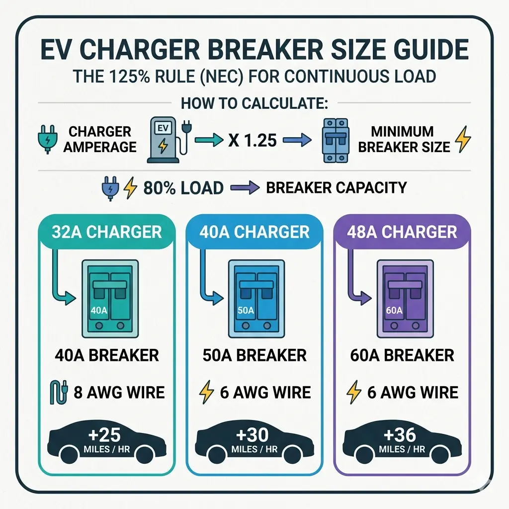
- Continuous Load Factor: For detailed thermal rules, read about proper breaker sizing for continuous loads. Under North American NEC rules, continuous loads require a 125% multiplier ($I_n \ge 1.25 \times I_{continuous}$). Under IEC/BS 7671 rules, devices are rated for their nominal current provided installation conditions and ambient de-rating inside the consumer unit are accounted for.
- Manufacturer’s Installation Manual (MIM): Most heat pump manufacturers explicitly state the required overcurrent protection device rating and trip curve (e.g., “Max fuse/MCB: 20A Type C”). Overriding this specification violates equipment listing and local regulations.
How Do You Calculate Current from Electrical Power?
Single-Phase Current Calculation:
$$I = \frac{P}{V \times \cos \varphi \times \eta}$$
Where:
• $P$ = Electrical input power (Watts)
• $V$ = Supply Voltage (e.g., 230V)
• $\cos \varphi$ = Power factor (typically 0.95–0.98 for modern EVSE switch-mode rectifiers; 0.85–0.92 for heat pump compressors)
• $\eta$ = Motor/Inverter electrical efficiency (typically 0.90–0.95)
Three-Phase Current Calculation:
$$I = \frac{P}{\sqrt{3} \times V_L \times \cos \varphi \times \eta}$$
Where $V_L$ = Line-to-Line Voltage (e.g., 400V).
Does an EV Charger Need a Dedicated MCB?
Yes. BS 7671 (Section 722.533.101), IEC 60364-7-722, and NEC Article 625.40 mandate that each EV connect-point must be supplied by its own dedicated final circuit protected by individual dedicated circuit breakers for EV chargers. An EV charger circuit must never supply any other socket outlet, light, or appliance.
Similarly, heat pump outdoor and indoor units must have a dedicated radial supply with an adjacent lockable local isolator (rotary switch) to allow safe mechanical maintenance without interrupting other dwelling circuits.
What MCB Characteristics Are Suitable for EV Chargers and Heat Pumps?
Selecting the nominal rating ($I_n$) is only half the task; matching your supply with 1P, 2P, 3P, and 4P circuit breakers and selecting the instantaneous magnetic tripping curve (Type B, Type C, or Type D according to IEC/EN 60898-1) is critical.
- Type B MCB (Trips at 3–5 $\times I_n$):
- Application for EVSE: Highly recommended and standard for residential EV chargers (unless manufacturer specifies otherwise). EV chargers do not possess magnetic inrush upon energization; power electronics ramp current smoothly. A Type B breaker provides rapid instantaneous disconnection during short-circuit faults, making it easier to comply with maximum earth fault loop impedance ($Z_s$) requirements.
- Application for Heat Pumps: Generally unsuitable for heat pumps, as compressor startup or auxiliary transformer energization can cause immediate magnetic nuisance tripping.
- Type C MCB (Trips at 5–10 $\times I_n$):
- Application for Heat Pumps: The industry standard choice for heat pumps, air conditioning systems, and motor loads. Handles moderate inductive inrush currents without tripping.
- Constraint: Because Type C breakers require higher fault current to achieve magnetic disconnection within standard disconnection times (0.4s for 230V TN systems under BS 7671), the maximum permitted $Z_s$ is significantly lower than for Type B (see table below).
- Type D MCB (Trips at 10–20 $\times I_n$):
- Reserved strictly for high-inrush industrial motor loads or large direct-online industrial heat pumps. Rarely used or permitted in domestic settings due to extremely restrictive $Z_s$ limits requiring very low loop impedance.
| MCB Rating ($I_n$) | Trip Curve | Magnetic Trip Range | Max Permitted $Z_s$ (0.4s Disconnect @ 230V, BS 7671) | Primary Residential Application |
|---|---|---|---|---|
| 16A | Type B | 48 A – 80 A | $2.73\,\Omega$ | 3.6 kW EVSE / Small Auxiliary Controls |
| 16A | Type C | 80 A – 160 A | $1.37\,\Omega$ | Small Inverter ASHP (up to 6 kWth) / 11 kW 3-Ph EVSE |
| 20A | Type C | 100 A – 200 A | $1.09\,\Omega$ | Medium Inverter ASHP (8 kW – 12 kWth) |
| 32A | Type B | 96 A – 160 A | $1.37\,\Omega$ | Standard 7.4 kW Mode 3 EVSE |
| 32A | Type C | 160 A – 320 A | $0.68\,\Omega$ | Large Single-Phase ASHP + Integrated Immersion Booster |
| 40A | Type B | 120 A – 200 A | $1.09\,\Omega$ | Dedicated Sub-panel feeder / 7.4 kW EVSE under NEC 125% rule |
| 40A | Type C | 200 A – 400 A | $0.55\,\Omega$ | High-capacity ASHP with dual-stage auxiliary elements |
What Cable Size Do You Need for an EV Charger and Heat Pump?
Conductor cross-sectional area cannot be selected by guesswork. It must be derived through a standardized multi-step calculation verifying current-carrying capacity ($I_z$), thermal de-rating factors, voltage drop ($V_d$), and short-circuit withstand capacity ($k^2 S^2 \ge I^2 t$).
Which Factors Determine the Required Cable Cross-Section?
The design current ($I_b$) is modified against installation conditions using standardized correction factors:
Tabulated Cable Current Capacity Requirement ($I_t$):
$$I_t \ge \frac{I_n}{C_a \times C_g \times C_c \times C_i}$$
Where:
• $I_n$ = Nominal rating of the protective device (MCB)
• $C_a$ = Ambient temperature correction factor (e.g., 0.87 for $40^\circ\text{C}$ ambient in lofts / plant rooms)
• $C_g$ = Grouping factor (derates conductors bunched with other loaded cables in trunking or conduits)
• $C_i$ = Thermal insulation factor (severe derating when cable passes through building insulation: $C_i = 0.5$ if fully enclosed >500mm)
• $C_c$ = Semi-enclosed fuse factor (1.0 for modern MCB/RCBO protection)
How Does Cable Length Affect Voltage Drop?
As cable length ($L$) increases, internal resistance increases, resulting in voltage drop between the distribution board and the load. Wiring standards stipulate maximum permissible voltage drop:
- BS 7671 / IEC 60364: Maximum 5% for low-voltage power/heating circuits (11.5V on a 230V supply). However, best practice for EVSE and heat pumps is to design for $\le 3\%$ (6.9V) to maintain high efficiency and prevent control board errors.
- NEC (Informational Note 210.19(A)): Maximum 3% on branch circuits and 5% total including feeder.
Voltage Drop Formula (Single-Phase):
$$V_d = \frac{(mV/A/m) \times I_b \times L}{1000}$$
Where:
• $mV/A/m$ = Millivolt drop per ampere per meter from standard cable tables (e.g., BS 7671 Appendix 4)
• $I_b$ = Circuit design current (Amps)
• $L$ = One-way circuit run length (Meters)
Step-by-Step Cable Sizing Workflow
Step 1: Determine Design Current ($I_b$) → Calculate equipment maximum running load ($I_b$).
Step 2: Select Protective Device Rating ($I_n$) → Choose nominal MCB rating such that $I_n \ge I_b$.
Step 3: Identify Installation Method & De-rating Factors → Establish Reference Method (e.g., Method C – Clipped Direct; Method A – Enclosed in conduit in insulated wall; Method 100#/101# – In loft insulation). Calculate total de-rating multiplier $C = C_a \times C_g \times C_i$.
Step 4: Calculate Required Tabulated Current ($I_t$) → $I_t \ge I_n / C$. Cross-reference with manufacturer/standard cable tables to select initial conductor cross-section ($S$).
Step 5: Calculate and Verify Voltage Drop ($V_d$) → Calculate $V_d$ using the $(mV/A/m)$ value for cross-section $S$. If $V_d > 3\%$ (or $5\%$), step up conductor size to the next larger cross-section (e.g., from $6\,\text{mm}^2$ to $10\,\text{mm}^2$) and re-verify.
Step 6: Verify Fault Loop Impedance ($Z_s$) & Disconnection Time → Confirm $Z_s = Z_e + (R_1 + R_2) \times L \le \text{Max Permitted } Z_s$ for the selected MCB.
Cable Sizing Comparison Table: EVSE vs Heat Pump Across Cable Lengths
The table below demonstrates minimum required copper conductor cross-sectional areas ($70^\circ\text{C}$ Thermosetting/PVC insulated multicore cable, Method C – Clipped Direct / Surface Mounted) under standard single-phase 230V conditions.
| Circuit Type | Design Current ($I_b$) | Recommended MCB | Run Length: 15 meters | Run Length: 30 meters | Run Length: 50 meters |
|---|---|---|---|---|---|
| 7.4 kW EV Charger | 32.0 A | 32A (or 40A) Type B | $6.0\,\text{mm}^2$ ($V_d \approx 3.51\text{V} / 1.5\%$) | $6.0\,\text{mm}^2$ ($V_d \approx 7.02\text{V} / 3.05\%$) | $10.0\,\text{mm}^2$ ($V_d \approx 7.04\text{V} / 3.06\%$) |
| 3.6 kW EV Charger | 16.0 A | 16A (or 20A) Type B | $2.5\,\text{mm}^2$ ($V_d \approx 4.32\text{V} / 1.9\%$) | $4.0\,\text{mm}^2$ ($V_d \approx 5.28\text{V} / 2.3\%$) | $6.0\,\text{mm}^2$ ($V_d \approx 5.84\text{V} / 2.5\%$) |
| Small ASHP (Inverter 6-8 kWth) | 12.0 A | 16A Type C | $2.5\,\text{mm}^2$ ($V_d \approx 3.24\text{V} / 1.4\%$) | $2.5\,\text{mm}^2$ ($V_d \approx 6.48\text{V} / 2.8\%$) | $4.0\,\text{mm}^2$ ($V_d \approx 6.60\text{V} / 2.9\%$) |
| Med ASHP + 3kW Boost | 24.0 A | 32A Type C | $4.0\,\text{mm}^2$ ($V_d \approx 3.96\text{V} / 1.7\%$) | $6.0\,\text{mm}^2$ ($V_d \approx 5.28\text{V} / 2.3\%$) | $10.0\,\text{mm}^2$ ($V_d \approx 5.28\text{V} / 2.3\%$) |
| Large ASHP (Single Phase) | 30.0 A | 32A / 40A Type C | $6.0\,\text{mm}^2$ ($V_d \approx 3.29\text{V} / 1.4\%$) | $6.0\,\text{mm}^2$ ($V_d \approx 6.58\text{V} / 2.8\%$) | $10.0\,\text{mm}^2$ ($V_d \approx 6.60\text{V} / 2.9\%$) |
Can Your Existing Consumer Unit Support an EV Charger and Heat Pump Upgrade?
Installing an EV charger alongside a heat pump often doubles the peak electrical demand of a single-phase dwelling. A thorough site audit of the upstream infrastructure is mandatory before executing final circuit work.
How Do You Calculate the Total Household Electrical Load?
Before assessing dual-load upgrades, see our guide on how to choose breaker size for household circuits
Electrical engineers and installers must perform a formal Maximum Demand Assessment taking into account permitted diversity:
- Standard Base Dwelling Load: Lighting (with diversity), cooking appliances, general ring socket circuits, shower units, and immersion heaters typically total 35A to 50A of diversified demand.
- Add EV Charger: +32A (Zero diversity allowed).
- Add Heat Pump: +16A to 28A (Zero diversity allowed for primary heating).
- Calculated Maximum Demand: $45\text{A} + 32\text{A} + 24\text{A} = \mathbf{101\text{A}}$.
Does Your Main Supply Have Enough Capacity?
Compare the calculated maximum demand against the dwelling’s incoming Distribution Network Operator (DNO) or utility cut-out service fuse:
- 60A Main Cut-out Fuse: Inadequate for simultaneous EVSE + Heat Pump installation. Upgrading the service fuse or installing active Dynamic Load Management is mandatory.
- 80A Main Cut-out Fuse: Marginal capacity. Will support both appliances only if household cooking/shower loads are modest or if an EV charger with load curtailment is utilized.
- 100A Main Cut-out Fuse: Standard residential ceiling for single-phase supplies. Capable of supporting both systems provided no other ultra-high loads (e.g., two electric showers + induction range) are energized simultaneously.
- Three-Phase 3x60A / 3x100A Supply: The ideal infrastructure solution. Consult our breakdown of single phase vs. three phase breakers to learn how to balance the EV charger across three phases (11 kW @ 16A/phase) and the heat pump across a separate phase.
When Is Dynamic Load Management (DLM) Necessary?
Dynamic Load Management utilizes an external Current Transformer (CT) clamp installed at the main incoming meter tails. The CT clamp continuously measures total household current in real time and communicates with the EV charger via Modbus RS485 or hardwired Ethernet.
If total dwelling current approaches the pre-set threshold (e.g., 72A on an 80A main fuse), the smart EV charger automatically reduces its charging current from 32A down to 24A, 16A, or 6A, or temporarily pauses charging. This guarantees the main fuse is never overloaded while giving heating (heat pump) priority over vehicle charging.
When Should You Upgrade the Consumer Unit / Electrical Panel?
An upgrade or installation of a dedicated secondary distribution enclosure is required when:
- There are no spare usable outgoing ways in the existing consumer unit.
- The main internal busbar rating is only 60A or 80A (modern boards must be rated at 100A minimum).
- The existing board uses outdated upstream Type AC RCDs that will be blinded by DC residual currents generated by the EVSE or inverter compressor.
- There is no integrated Type 2 Surge Protection Device (SPD), which is now mandatory under BS 7671 (Amendment 2) and international equipment safety standards to protect sensitive inverter and EV control boards.
What Are Common MCB and Cable Sizing Mistakes?
Electrical inspectors and warranty engineers frequently encounter systematic installation errors. Avoiding these six pitfalls ensures compliance and system longevity:
1. Sizing Breakers Based Only on Equipment Nameplate kW Rating
Electricians often calculate current as $P/V$ (e.g., $7,000\text{W} / 230\text{V} = 30.4\text{A}$) and erroneously install a 30A or 32A breaker for continuous equipment without considering thermal de-rating inside the enclosure, or forgetting the 125% continuous load rule under NEC frameworks.
2. Ignoring Cable Run Length and Voltage Drop
Selecting a $6\,\text{mm}^2$ cable for a 32A EV charger is standard for short runs (<20m). However, installing $6\,\text{mm}^2$ on a 45-meter detached garage run causes voltage drop to exceed $4.5\%$, inducing thermal buildup and triggering under-voltage charging faults in modern EVs.
3. Overlooking Thermal Loft Insulation and Cable Grouping
Routing a twin-and-earth or multicore cable through 300mm of glass mineral wool loft insulation without applying thermal de-rating factor $C_i$ cuts the cable’s current-carrying capacity by up to 50%. A $6\,\text{mm}^2$ cable enclosed in thermal insulation (Reference Method 101#) has a tabulated capacity of only 27A—grossly inadequate for a 32A continuous EV load, creating a severe fire hazard.
4. Ignoring Heat Pump Auxiliary Heaters and Defrost Current Spikes
Sizing the heat pump breaker solely for the compressor (e.g., 16A) results in immediate breaker tripping during mid-winter sub-zero defrost cycles when the integrated 3 kW or 6 kW auxiliary electric heater engages.
5. Selecting the Wrong MCB Tripping Curve
Installing a Type B MCB on a non-inverter heat pump leads to nuisance tripping due to compressor inrush. Conversely, installing a Type C or Type D breaker without verifying maximum earth fault loop impedance ($Z_s$) creates a non-compliant installation where fault disconnection times fail to meet safety limits.
6. Overlooking EV Residual Current Protection (DC Leakage)
Standard Type AC or standard Type A RCDs are blinded by smooth DC fault currents exceeding 6mA produced by EV battery charging rectifiers. Review our selection guide on RCD types for EV charging to ensure the circuit includes a dedicated Type B RCD or a Type A RCD/RCBO combined with a 6mA RDC-DD complying with IEC 62955 / BS 7671 Section 722.531.3.101.
What Electrical Standards Apply to EV Chargers and Heat Pumps?
| Jurisdiction / Standard | EV Charger (EVSE) Requirements | Heat Pump / HVAC Requirements |
|---|---|---|
| United Kingdom (BS 7671:2018+A2:2022) | • Section 722 dedicated radial circuit requirement. • Type A RCD + 6mA RDC-DD or Type B RCD. • PME/PEN fault protection (Regulation 722.411.4.1) for outdoor charging. • Type 2 SPD mandatory under Section 443. | • Dedicated radial circuit; lockable local rotary isolator. • Verification of $Z_s$ for Type C MCBs. • Integration with Building Regulations Part L / Part P. • Heat pump auxiliary booster load accounting. |
| North America (NEC / NFPA 70) | • Article 625: Continuous load sizing (125% ampacity multiplier). • Dedicated branch circuit (Article 625.40). • GFCI Class A (6mA trip) personnel protection. • Sizing breaker to 40A or 50A for a 32A/40A continuous charger. | • Article 440 (Air-Conditioning & Refrigerating Equipment). • Sizing conductors to Minimum Circuit Ampacity (MCA). • Sizing overcurrent protection to Maximum Overcurrent Protection (MOP). • Disconnecting means within sight of unit (Article 440.14). |
| International / Europe (IEC 60364 / EN Standards) | • IEC 60364-7-722 dedicated final circuits. • IEC 61851-1 conductive charging system compliance. • IEC 62955 RDC-DD residual DC protection. • Compliance with local grid connection codes. | • EN 378 (Safety and environmental requirements for heat pumps). • IEC 60335-2-40 electrical appliance safety. • Harmonic distortion and flicker limits (EN 61000-3-2 / EN 61000-3-11). |
Recommended Internal Linking Structure
| Topic Cluster / Target Concept | Recommended Anchor Text | Technical Context & Purpose |
|---|---|---|
| Continuous Load Sizing Rules | proper breaker sizing for continuous loads | Explains thermal de-rating rules for sustained electrical loads |
| Dedicated Circuit Protectors | dedicated circuit breakers for EV chargers | Details dedicated radial circuit rules under Section 722 & NEC 625 |
| Residual Current Engineering | RCD types for EV charging | Analyzes Type A, Type B, and 6mA RDC-DD DC blinding protection |
| Protective Device Comparison | MCB vs RCBO for EV chargers | Compares single-module RCBOs with separate MCB+RCD configurations |
| Household Load Calculations | how to choose breaker size for household circuits | Connects domestic diversity calculations and panel capacity audits |
| HVAC Electrical Sizing | what size MCB for a heat pump | Provides in-depth analysis of MCA, MOP, and compressor inrush protection |
Frequently Asked Questions (FAQ)
1. What Size MCB Do I Need for a 7.4 kW EV Charger?
Under BS 7671 and IEC standards, a standard single-phase 7.4 kW EV charger drawing 32A requires a 32A or 40A Type B MCB / RCBO on a dedicated circuit. Under North American NEC rules, because an EV charger is classified as a continuous load, you must apply the 125% rule ($32\text{A} \times 1.25 = 40\text{A}$), requiring a 40A double-pole circuit breaker.
2. What Cable Size Is Required for a Home EV Charger?
For a standard 32A (7.4 kW) single-phase EV charger, a $6.0\,\text{mm}^2$ copper conductor (or 8 AWG) is the industry standard for cable lengths up to 25–30 meters (clipped direct). For runs exceeding 30 meters, or where cables pass through thermal loft insulation or grouped conduits, you must step up to $10.0\,\text{mm}^2$ (or 6 AWG) to prevent excessive voltage drop and thermal de-rating.
3. What Size Breaker Does a Residential Heat Pump Need?
Breaker sizing depends strictly on the manufacturer’s Maximum Overcurrent Protection (MOP) nameplate rating. A typical residential 6 kW–8 kW (thermal) inverter heat pump generally requires a 16A or 20A Type C MCB. Systems equipped with integrated 3 kW to 6 kW electric auxiliary/defrost immersion heaters require a 32A or 40A Type C MCB.
4. Can an EV Charger and Heat Pump Share One Circuit?
No. Both international wiring regulations (BS 7671 Section 722, NEC Article 625, IEC 60364) and HVAC electrical standards strictly prohibit sharing circuits. Each device must be supplied by its own independent, dedicated radial circuit protected by a dedicated overcurrent and residual current protective device.
5. Can My Existing Consumer Unit Support Both an EV Charger and a Heat Pump?
Your existing panel can support both upgrades only if: (1) It has at least two spare outgoing ways; (2) The internal busbar is rated at 100A; (3) The incoming service cut-out fuse is rated at 80A or 100A; and (4) Proper residual current (Type A/B) and Surge Protection (SPD) are present. If the panel is full or rated for 60A, you must either upgrade the main board, install a dedicated secondary EV/Heat Pump sub-panel, or deploy Dynamic Load Management.
6. Does a Longer Cable Run Always Require a Larger Conductor Cross-Section?
Yes. Conductor resistance increases proportionally with length ($R = \rho \cdot L / A$). On long runs, even if a $4.0\,\text{mm}^2$ or $6.0\,\text{mm}^2$ cable has adequate thermal current-carrying capacity, voltage drop can exceed the recommended 3% threshold, resulting in operating errors, electronic brownouts, and reduced appliance efficiency. Increasing cross-section is the standard engineering solution to mitigate voltage drop.
7. Does an EV Charger Need an RCBO Instead of a Standard MCB?
Yes, an RCBO (combining overcurrent and 30mA residual current protection in a single module) is the preferred engineering choice. Furthermore, the residual protection must be either a Type B RCBO or a Type A RCBO combined with a 6mA RDC-DD to protect against smooth DC fault currents from the EV battery charger that can blind upstream household RCDs.
8. Can Dynamic Load Management Avoid an Expensive Electrical Supply Upgrade?
Yes. Dynamic Load Management (DLM) monitors total household current via an incoming CT clamp. When concurrent household demand (heat pump, electric cooking, water heating) approaches the main service fuse limit (e.g., 60A or 80A), the EV charger automatically throttles back its current draw. This avoids main fuse overload and eliminates the immediate need for a costly utility service or three-phase supply upgrade.